TL;DR:
An EMI filter is one of the most measurable products in all of audio: known signal in, measured signal out, and the difference reported in dB across a frequency range. Yet the audiophile Ethernet filter market runs almost entirely on adjectives and superlatives, often with no attenuation curves, no frequency ranges, and no test methods. Just listening impressions, fancy cases and marketing.
We know because we submitted our own filter for review and were told it added “perkiness.”
The reality is you may not need an Ethernet EMI filter at all. You might need a $2 ferrite. But if you shop for one, ask the four questions this market doesn’t answer:
- How many decibels?
- Across what frequency range?
- In which mode, common or differential?
- Measured how?
If a company can answer those questions, you can compare filters. If it can’t, you’re comparing stories, and EMI doesn’t care how good the story is.
Our numbers: More than 100 dB of insertion loss from 50 Hz to 40 GHz, measured line-to-ground (common mode) using a method based on MIL-STD-220. Because the ACTIV regenerates the signal instead of passing it through, differential-mode noise doesn’t get across either. And yes, we’ll happily show you the curve.
1. An Unusual Corner of the EMI Business
I remember receiving the email asking if our GigaFOIL Ethernet filter would make a streaming audio system sound better. My honest first reaction: it’s a digital signal, checked for errors, carrying essentially bit-perfect audio over balanced twisted-pair CAT6 cable. Probably not. He insisted on trying, so we lent him one. The review came back glowing.
So we reconsidered the physics and figured maybe noise hitchhikes from the digital side to the analog side, and our filter was interrupting that ride. Word got out, and audiophiles started buying our GigaFOILv4-INLINE, a filter we originally designed for industrial automation, where Ethernet-controlled tools hiccup in EMI-soaked factories. The “INLINE” installs in the middle of the Ethernet cable. Apparently, it worked just as well beside a DAC as beside an arc welder. It was mocked for looking like someone made it in high school metal shop (hurtful, but fair; it was an industrial filter made of soldered galvanized sheet metal), but it worked! And it was easily the highest-performing Ethernet EMI filter available on the market in 2018.
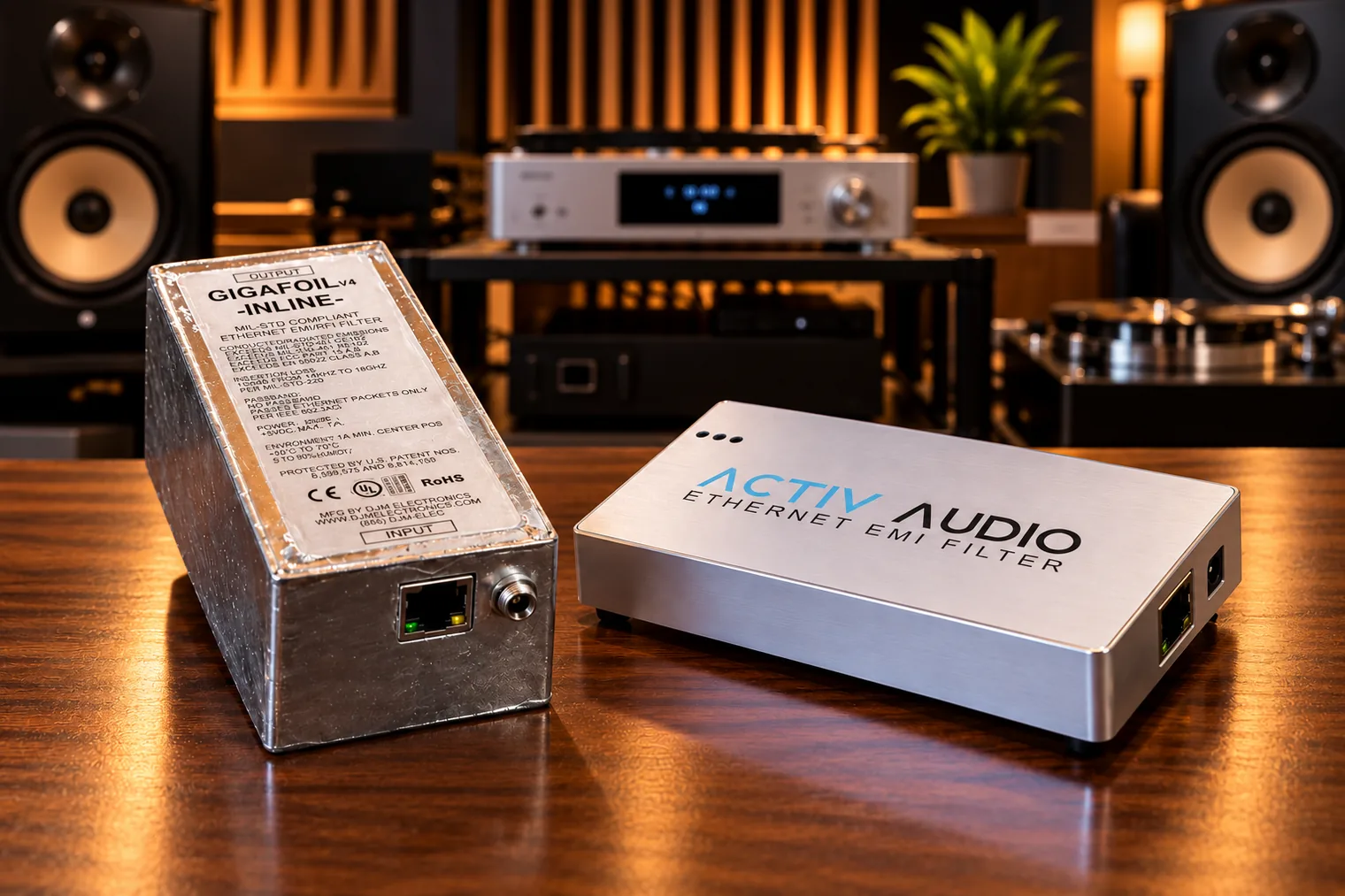
In 2022, we designed our next generation of EMI filters: the ACTIV product line. Digital signal processing. 10-gigabit Ethernet. 100 dB of insertion loss across a frequency range extending from 50 Hz to 40 GHz. This time we built a pretty audiophile version, the ACTIV AUDIO, and submitted it for review ourselves.
We received the two strangest reviews we’ve ever seen. The first reviewer simply listened with and without the filter (not even a blind test) in a rural home he said might be too quiet for EMI to matter. No measurements, two network switches as the comparison, and a favorable verdict: our filter added a bit of “perkiness and illumination.” A positive review, to be sure, but we have been writing filter specifications for decades, and “perkiness” has never appeared on one. The second reviewer had a real audio analyzer, but tested an EMI filter without establishing any EMI to filter. He let his readers vote, and the verdict came back “Poor” for not fixing a problem that wasn’t there. Even when he draped a noise source over the Ethernet cable and was able to show our filter attenuating the interference exactly as designed, the prevailing verdict stayed “Poor.”
One reviewer heard a difference without measuring the interference. The other measured no interference and still demonstrated that the filter worked anyway. Neither of them evaluated an EMI filter as an EMI filter.
Feeling confused and a little deflated, we took a closer look at this market to see what was going on. Here’s what makes it strange: audiophiles already know how to test equipment. This industry bench-tests everything. An amplifier review comes with clipping power at a stated distortion, both channels driven, into real loads. A speaker review comes with frequency response curves, sensitivity, and distortion at volume. And then the same market reviews an Ethernet EMI filter — a device whose entire job can be expressed on an attenuation curve — with no measurements at all. Amplifiers get an autopsy. Filters get a séance.
So what fills the space where the numbers should be? We surveyed the Ethernet filter market and found marketing doing the work of measurement:
- A flagship passive filter costing over $2,000 touts an “8-core architecture” and a “proprietary filter system,” hand-wired from high-purity conductors, and publishes no attenuation figure at all (in fact, their case is welded shut so you can’t take a look even if you wanted to!).
- One product line boasts “premium galvanic isolation technology.” Galvanic isolation through transformer magnetics is already fundamental to standard copper Ethernet interfaces. It’s not premium, it’s not optional, and it’s not proprietary.
- A Danish manufacturer specifies its noise reduction not in decibels but in coil count. The entry model, at a mere $2,000+, carries 12 “Active Square Tesla Coils.” The promised result: “virtually no noise.” The measured result: no idea, at any price, at any coil count.
- A LAN silencer advertises “Zero-jitter memory buffers,” which is a fancy way of describing what a buffer is supposed to do. It’s like advertising “round wheels.”
- And the best one: the most engineering-minded filter product in the space that actually does publish real numbers. But the numbers are for its clock — the phase noise of its oscillator, presented as if it were filter performance. It isn’t. In a properly buffered asynchronous streaming architecture, the DAC ultimately clocks the audio with its own local clock rather than the Ethernet switch’s oscillator. You can put a cesium fountain clock in your switch, accurate to one second in 300 million years, and the DAC and your music would never know the difference. A clock is not a filter.
The enthusiasts? They’re the victims here, chasing perfect sound the way some men chase the perfect lawn. But they’ve been given nothing concrete to compare. As an EMI filter company, we test our filters using a universal method based on MIL-STD-220, the military’s accepted standard for measuring EMI filters and the yardstick used on the filters guarding the government’s most secure facilities. NIST-traceable instruments. A 100 dB+ shielded room. Calibrated fixtures. Reference antennas. Known signal in. Measured signal out. And the difference goes in a signed report any RF engineer can reproduce.
The audiophile market doesn’t have that. It has a “feeling.” Two publications reviewed a filter, and neither measured filtration. The buyer isn’t confused because he’s gullible. He’s confused because “confusion” has become part of the product.
2. Real Physics, Missing Numbers
Let’s be honest about the mechanisms, because they’re real. Ethernet was designed by some very smart people and it is impressively resistant to electromagnetic interference. The isolation magnetics in every Ethernet circuit are extremely effective, but the transformer has parasitic capacitance between its windings, and high-frequency common-mode energy can slip across. Switching-supply leakage rides cables and ground structures. RF can rectify in nonlinear circuitry and reappear at lower frequencies. Fiber can help clean that up, but the media converter on each end is a noisy transmitter with its own power supply reinjecting noise back onto the copper. Sure, there could be noise. There probably is noise. Noise is everywhere.
Whether it matters is another story. Maybe your building’s electrical wiring runs two feet behind your system in your Manhattan apartment. Maybe you’re on a farm with nothing to filter. Maybe the noise is real and your system can’t reveal it.
Many things can be true at the same time:
- bit-perfect transmission doesn’t prove the absence of electrical noise;
- electrical noise doesn’t prove corruption of the analog output;
- corrupted analog output doesn’t prove you can hear it.
That’s the pattern behind most of the products we surveyed. The physics isn’t false. The sin is using true mechanisms to imply sonic results that have never been quantified. Plausibility is not proof.
To see what’s really happening, let’s go back to the beginning: what a filter is, what it does, and what you’re actually paying for.
3. Trapdoors, Walls, and the Doorway Problem
A conventional passive filter is built from two basic components, and you can understand both in a paragraph.
A capacitor is like a tiny battery. Feed it a slow signal and it tops off, and once it’s full the current stops. The door closes. But hit it with a high-frequency signal and the voltage reverses so fast the capacitor never finishes charging. A capacitor that never finishes charging is, for all practical purposes, a short circuit. So we hang one between the signal line and ground: slow signals see a closed door; fast noise sees a trapdoor straight to ground. An inductor performs the same trick in reverse. It’s a coil whose magnetic field resists change in current. Slow signals barely notice and pass right through like it’s a simple wire. Fast signals are constantly changing, and the inductor fights every change. A wall. A capacitor gives high-frequency noise a trapdoor to ground. An inductor puts a wall in its path.
That’s the simplified physics, and now you probably know more about filter design than several manufacturers we just discussed.
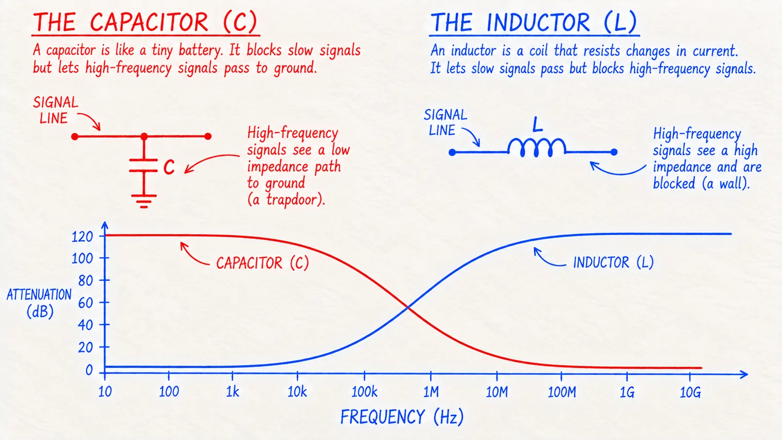
Every filter has a résumé: the “insertion loss curve” (or sometimes “rejection curve”). It’s a graph with frequency running left to right and the amount of signal that gets removed (the attenuation) running up and down. The flat part is the “passband,” where your signal lives untouched. The cliff is the transition. The floor is the “stopband,” where the noise goes to die.
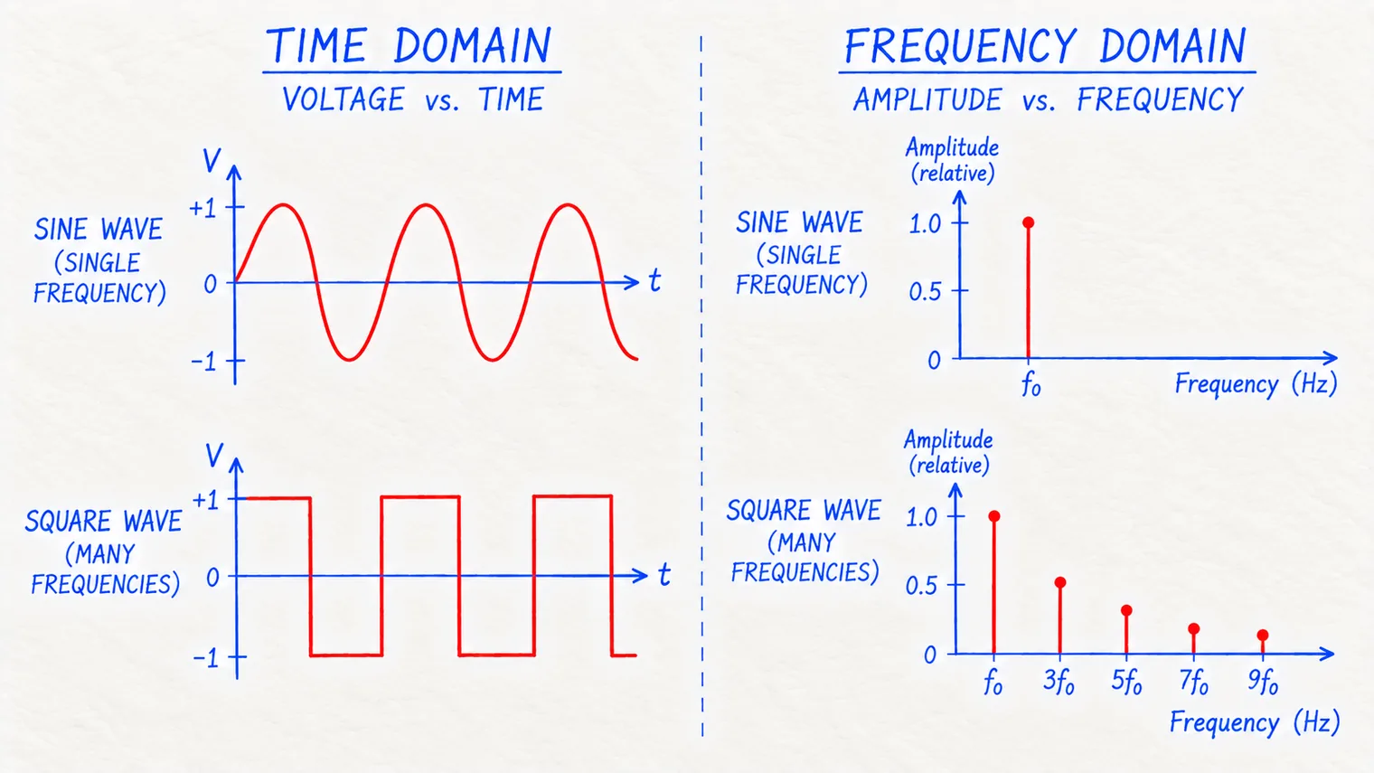
Now the complication that makes Ethernet genuinely hard. Filtering an analog audio line is easy: the single signal sits in a well-defined place, so you create a tight passband and wall off everything below and/or above it. Ethernet takes away that luxury, because a digital square wave is made up of a lot of different signals. A square wave is built from a fundamental plus a stack of higher frequency odd harmonics, and those harmonics are what keep the edges sharp and the timing crisp. Filter them off and the edges smear, the timing collapses, and the network starts choking on errors. (Real Ethernet uses clever multi-level encoding, and each generation gets more and more clever, but the filter design problem is the same.) So where an analog filter guards a narrow window, an Ethernet filter must hold open a doorway hundreds of megahertz wide, and, unfortunately, noise walks through that enormous doorway holding the data’s hand.
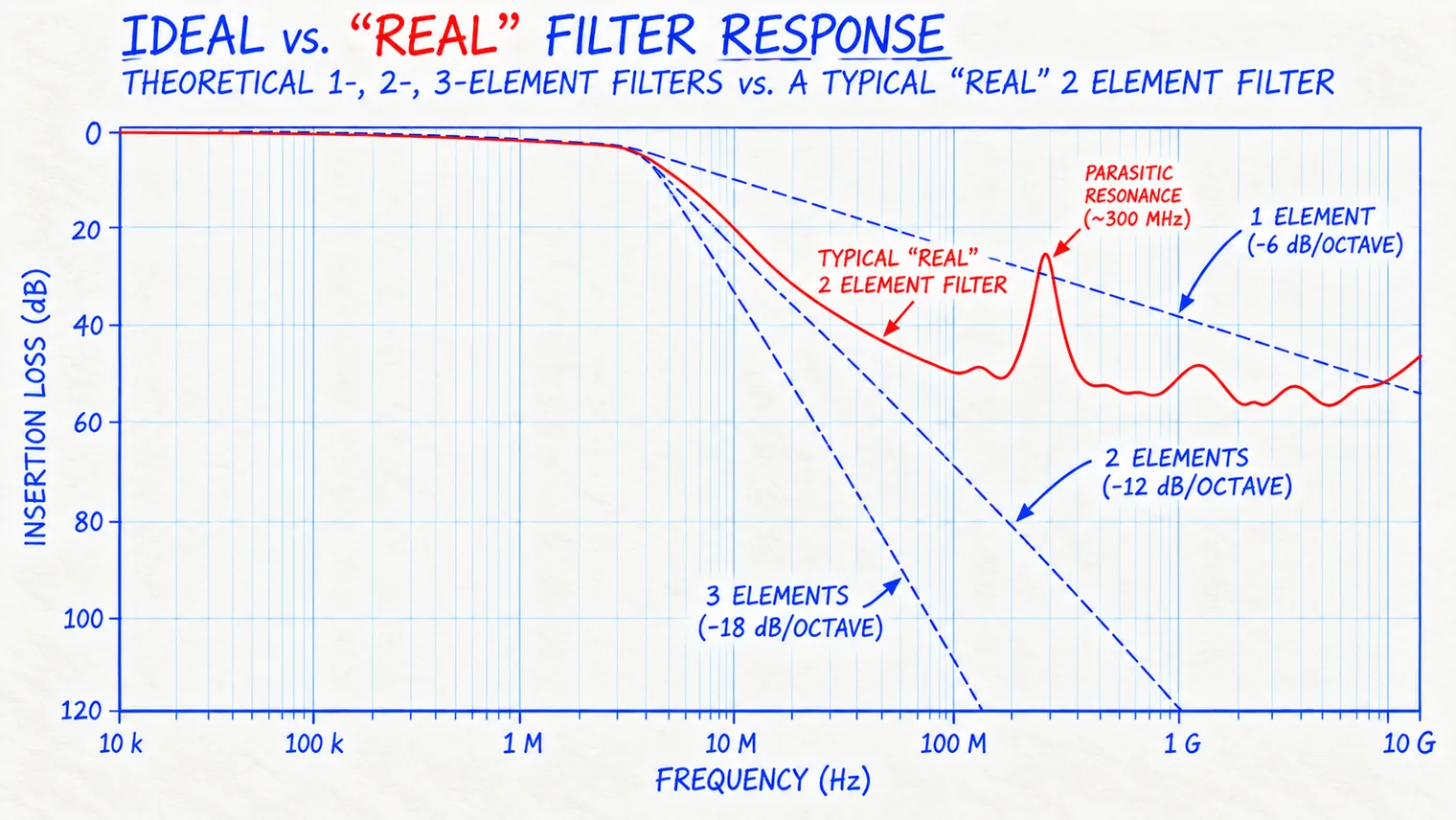
In order to work at all, an Ethernet filter must start filtering as much as possible at the lowest frequency possible without disrupting the square wave. The steepness of the insertion loss curve depends on the filter design. In the textbook version, each additional filter element can steepen the cliff by about 6 dB per octave: one is a slow incline, two a hillside, and three a wall. Sounds simple, but in real life every inductor is part capacitor, every capacitor is part inductor, and every component resonates somewhere. Start stacking multiple stages and the parasitic effects start fighting each other instead of the noise. At gigabit speeds, the geometry of the filter itself joins the circuit: traces, connectors, even the enclosure become unintended microwave components. It gets super complicated, super fast.
(One freebie for the designer: Ethernet data travels differentially — paired conductors swinging in opposition — while most conducted EMI travels common-mode, everything moving together. Attack the common-mode noise and the data never notices. That’s what a $2 ferrite does: a few honest dB for pocket change.)
4. What Are You Paying For?
Legitimate passive filtering has real costs. More stages mean more components, tighter tolerances, more modeling, and test equipment that costs more than a car. At less than $1,000, our Pasif 1G delivers more than 80 dB of insertion loss from 550 MHz to 40 GHz and more than 90 dB from 700 MHz to 30 GHz, while remaining transparent to the network at Gigabit speeds. We haven’t found another passive Ethernet filter with a published attenuation curve that beats it. If there is one, we’d genuinely like to see it.
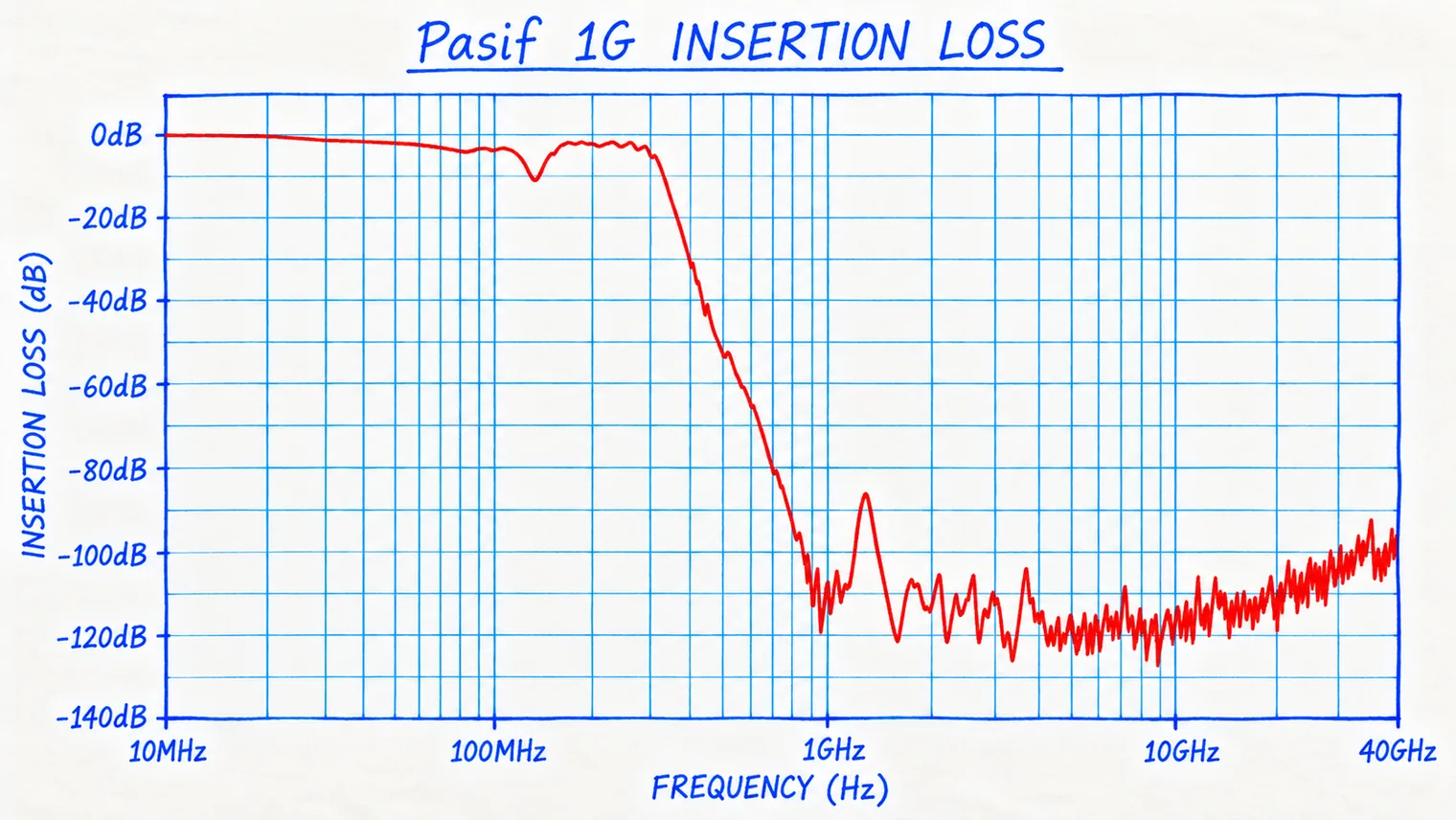
But in the audiophile market, price is a poor guide to filtering performance. In a recent spot check, passive Ethernet products ran from about $300 to over $4,000. One had an elaborate four-stage architecture with no attenuation curve. Another had proprietary multi-core filtering with extensive listening impressions, but no rejection numbers in dB and no frequency range. A third published clean data-path figures, but not the performance data that might justify the investment. What drives those prices? My guess is machining, finishing, packaging, marketing, dealer margins... nothing that adds a decibel of filtering or guarantees better sound. You’re not paying for attenuation. You’re paying for the anodizing.
We know, because we’ve done it. The ACTIV AUDIO uses the same core filtering architecture as our standard ACTIV 10G filter in an enclosure designed to look at home beside expensive audio equipment, and the prettier case raised the price by hundreds of dollars. Our premier Ethernet filter became more expensive when we made it look less like a filter and more like our competition.
5. No Doorway. No Hallway.
But honesty cuts both ways, so here’s the confession: even our Pasif 1G obeys the passive ceiling. The doorway is still open. It has to be. A passive filter can only attenuate outside the doorway it holds open, and a digital signal fills that doorway from the bottom up. A passive design can’t chase noise down into the low frequencies without eating the data it’s supposed to pass, and that low territory is exactly where mains leakage and power-supply residue live. If a filter isn’t powered (i.e. “active”), it is bound by these limits.
The ACTIV filters are a fundamentally different animal. At a high level, the architecture is simple: receive the Ethernet communication, recover the digital information, and regenerate it through an active system running on cleaned power. Digital signal processing preserves the data. Purpose-built microwave filter structures seal every other path across the boundary: power, ground, parasitic coupling, the enclosure itself. The entire body of the filter maintains the isolation. Regeneration alone isn’t a barrier; the performance comes from the complete electromagnetic architecture, not one chip or one choke.
Here’s what that buys using the terms I’ve been throwing around so nonchalantly. In dB, 3 dB cuts noise power in half. 20 dB is a hundred to one, a respectable spec for many filters. Our ACTIV filters provide 100 dB — a ten billion to one reduction in noise. That’s a jet engine at takeoff reduced to a library reading room. And not just over a minuscule stopband. They filter across the entire measured range of 50 Hz to 40 GHz (because that’s where our instruments stopped). From deep inside the audible range to satellite frequencies: silence.
A passive filter holds a door open and hopes. The ACTIV removes the doorway, and the hallway leading to it.
6. Ask for the Numbers
Here’s the part where we’re supposed to tell you to buy the biggest filter we make. We won’t, because you may not need it. You may have no meaningful EMI. Your equipment may already reject it. Any change may be inaudible, or beyond what your system can reveal. You might need a $2 ferrite. You might need nothing at all. Maybe you live on a farm.
But if you shop, shop like an audiophile. Smart amplifier buyers don’t just ask for watts; they ask watts into what load, at what distortion, both channels driven. Smart speaker buyers ask for frequency response with the tolerance, because 20 Hz to 20 kHz means nothing and plus-or-minus 3 dB means everything. A filter is the same sentence: dB means nothing without the band, the mode, and the method.
We publish our numbers. If you want our highest-performing filter in your audio system, you don’t need the audiophile wardrobe. Our standard ACTIV 10G uses the same core filtering architecture as the ACTIV AUDIO and was designed to protect Ethernet penetrations in shielded facilities where EMI performance actually has to be measured.
But whether you buy ours or somebody else’s, ask for the missing numbers.
Four questions:
- How many decibels?
- Across what frequency range?
- In which mode, common or differential?
- Measured how?
If a company can answer those questions, you have something you can compare. If it can’t, you’re not comparing filters. You’re comparing stories. And EMI doesn’t care how good the story is.
Where This Applies
Measured filtering for streaming audio systems:
Want the Curve?
Ask for the insertion loss data on any of our filters. We’ll send the decibels, the frequency range, the mode and the test method.