TL;DR:
- Fiber is an excellent transmission medium, but a Fiber penetration is more than a simple glass filament – it's a system requiring media converters, SFP transceivers, power supplies, patch cords and a waveguide.
- The waveguide can be the biggest weakness. A waveguide pipe big enough for a fiber connector can result in a Cutoff Frequency below modern threat frequencies. Packing the waveguide with cables moves the Cutoff Frequency lower still. And inadvertently using fiber cable with a single protective metallic element hidden in that cable eliminates the Cutoff entirely and allows all frequencies through the waveguide.
- Media converters are powered transmitters living inside your shield. They don't pass PoE (Power over Ethernet), they can overheat and fail quietly, and the emergency replacement can easily be whatever no-name brand ships fastest.
- Common CAT cabling with a tested signal line filter like DJM Electronics’ ACTIV 10G or ACTIV POE provides a known shielding effectiveness and frequency range, and can be an equivalent or better solution to Fiber. This is particularly true when any of the following applies: the run is short, the endpoints are copper, PoE is required, conversion would put active equipment inside the room or the signal is anything other than native optical Ethernet.
Introduction
Ask anyone in the SCIF world how to get a network connection through the wall of a shielded room and you will get the same answer before you finish the question: Fiber. Run fiber through a waveguide. Done. We call this the “Fiber Default.” It is the reflexive assumption among Accrediting Officials (AOs), Certified TEMPEST Technical Authorities (CTTAs), designers and installers that Fiber is always the safest answer at the shield boundary.
To be fair, Fiber earned its reputation, and the Fiber Default exists for good reasons. There is nothing wrong with a default, as long as the trade-offs are actually understood. And typically on this topic they are not. Even veteran accreditors have publicly warned against leaning on the "it's fiber, so it's okay" mantra.
The goal of this paper is to try and explain some of these trade-offs. It is written primarily for the SCIF (Sensitive Compartmented Information Facility) and SAPF (Special Access Program Facility) industry, but the physics is universal and applies to all RF shielded enclosures and test chambers. And don’t worry, this is not a “physics” paper, and we’ll leave most of the equations in the books where they belong.
Fiber Can Be an Excellent Choice
Credit where it's due. Fiber is the right answer for a lot of jobs.
- Long Runs. Between buildings, across a campus, down a trunk line, Fiber wins. No contest.
- High-bandwidth Backbone Links. If both ends are switches with SFP ports (the plug-in optical modules), native optical Ethernet is clean, fast and mature.
- No Conductive Path / Galvanic Isolation. Glass does not conduct electricity. A fiber strand does not put copper through your perimeter, carry common-mode current, create a ground loop or act as an antenna. That is a great attribute and tough to compete with. And for sites with real ground-potential differences, that alone can justify it.
- EMI Immunity. The optical signal does not care about the electric and magnetic fields that induce voltages on metallic conductors. In a high-EMI environment, that matters.
- Simplified Paperwork. A nonconductive penetration usually requires less analysis than a metallic one. The official SCIF TEMPEST checklist from the ODNI literally says if the signal line is "Fiber Optic, skip to 2." When the form itself waves you through, that is a genuine project advantage and we will not pretend otherwise. Just keep in mind that "easiest to approve" and "best engineered" are two different claims.
The Real Comparison
Here is the part that gets skipped: “Fiber” is more than a simple transmission medium, it requires a system. The moment either endpoint has an RJ45 jack or speaks anything other than native optical Ethernet, that simple strand of glass starts collecting hardware: media converters, SFP transceivers, power supplies, patch cords and a waveguide to get through the wall.
So the honest comparison is never "Fiber vs Copper." It is an uncharacterized system of conversion hardware, optical interfaces and a waveguide, versus a standard copper cable passing through a tested signal line EMI filter with a known shielding effectiveness and frequency range. Nobody tested your Fiber setup as a system. Somebody did test the filter.
Now let’s walk through your Fiber system.
Waveguide 101
The “Magic Pipe.” Every SCIF or shielded room has a few: short metal tubes through the wall that pass fiber, water or air while somehow not leaking RF. It looks like a pipe, but it is not just a pipe. It is a trick of physics where the geometry of the pipe is the “magic.”
The uncomfortable part. Normally, a metal tube is a conduit for radio waves, not a barrier. Microwave engineers build them on purpose to move RF from one place to another. They call them “wave-guides” because they guide the radio waves from Point A to Point B with almost no loss.
Now the catch. To travel down the tube, a wave has to fit, and "fit" has a specific meaning. Metal walls force the electric field to zero at their surface. The field is pinned at both walls the way a guitar string is pinned at both anchor points. The simplest pattern that starts at zero, does something in the middle and returns to zero is half a sine wave. So half a wavelength has to fit across the tube opening. A tube passes any wave shorter than 2 × its Width and blocks everything longer. The dividing line is the “Cutoff Frequency,” which is why the tubes on your SCIF are formally called “Waveguides Below Cutoff.” Waves too big to fit do not get attenuated a little, they get completely bounced. Think of the amusement park sign, in reverse: “you must be smaller than this to ride.” And for completeness: the tube’s length determines how much attenuation you get below cutoff (longer tube, stronger bounce), but it is the diameter that sets the Cutoff Frequency, so that is the number we will follow from here.
About that 1.7. Normally, “waveguides” are square or rectangular. The tube in your SCIF is missing the corners a square would have, so it acts about 15% narrower than its diameter. Cutoff wavelength for a circular waveguide ≈ 1.7 × Diameter, not the 2 × Width of the square waveguide.
And some handy arithmetic:
Wavelength in inches ≈ 11.8 ÷ frequency in GHz
Cutoff Frequency in GHz ≈ 6.9 ÷ waveguide diameter in inches.
That’s it for the math. Promise!
| Waveguide Diameter | Cutoff Frequency (Air-filled) |
|---|---|
| 0.25" | 27.7 GHz |
| 0.5" | 13.8 GHz |
| 0.75" | 9.2 GHz |
| 1" | 6.9 GHz |
| 1.5" | 4.6 GHz |
| 2" | 3.5 GHz |
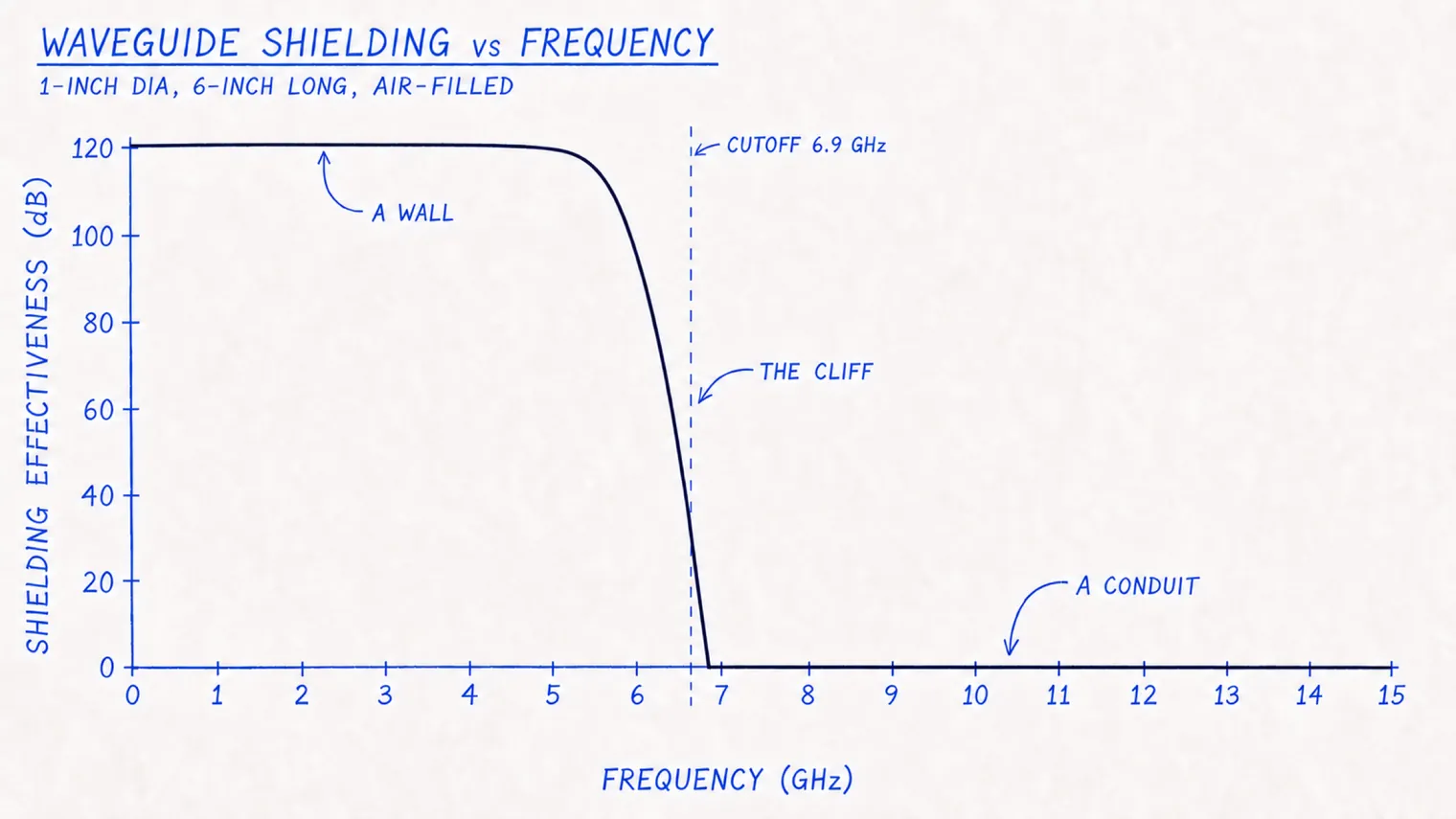
The Cliff. Below cutoff, a wall. Above cutoff, a conduit. There is no gentle rolloff and no partial credit. A waveguide is not a gradual slope, it is a Cliff. For a typical 6-inch long, 1-inch diameter pipe, 6 GHz is still hitting a wall: over 95 dB of attenuation. Cross the 6.9 GHz cutoff and the pipe stops rejecting energy and starts carrying it with little or no loss. Keep that Cliff in mind, because the next section is about how it moves.
Three Ways the Magic Fails
Each of these is worse than the last.
1. The Connector Problem (Moves the Cliff Closer)
Open wide. A waveguide for fiber has to be large enough to swallow the fiber connector. The common dual SC connector needs a 1” pipe to fit through (cutoff 6.9 GHz). Even a bare simplex SC realistically needs a 0.75" diameter (cutoff 9.2 GHz). Compare that against NSA 94-106's 10 GHz shielding requirement and threat frequencies that now extend to 40 GHz. The waveguide vendors concede it themselves: once the pipe diameter passes a half inch, 100 dB at 10 GHz is not realistic.
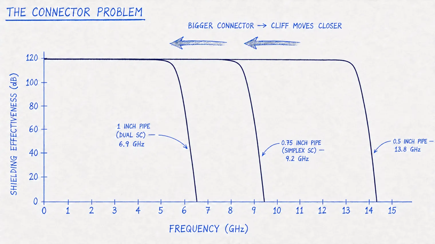
The obvious fix. Switch to the smaller LC connector (roughly 0.5” diameter for a dual connector), and it helps, some. But a smaller diameter means the same cable now fills a much larger percentage of the opening, which leads directly to the next problem.
2. Dielectric Loading (Moves the Cliff Closer Still)
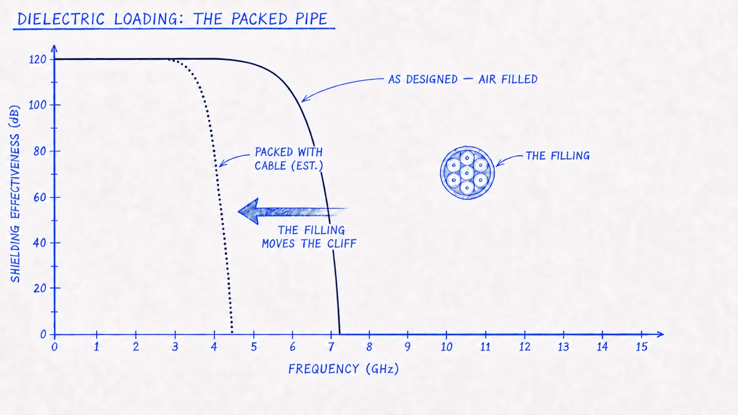
The filling matters. All of that cutoff math assumed an air-filled tube. Your tube is not filled with air. It is packed with the fiber, jacket, and maybe some aramid yarn. Any insulating material the wave passes through will shorten the wavelength. Shorter waves fit through smaller openings. Fill the tube, and waves that could not fit before now can (Cutoff Frequency drops by the square root of the fill's dielectric constant – you don’t need to remember that, but keep it in mind next time you pack your waveguides full of fibers!). The U.S. Army measured this in 1984 and concluded that generally, any fill besides air lowers the Cutoff Frequency and, for the wrong materials, can compromise the effectiveness of the shield. The physics has been known for forty years, but nobody is calculating this in the field.
It gets better. A 2018 Army study measured commercial off-the-shelf penetrations and found the as-built Cutoff Frequency was measurably below the predicted value just because of manufacturing variability. And that was before anything was pulled through them, so the margin you think you have may not exist.
A Short Word About How Fiber Gets Protected
Fiber is delicate. It has bend radius limits, it does not love being pulled and it really does not love being crushed or kinked. So in the real world it gets protected: jacketed, reinforced, armored. Perfectly sensible. Hold that thought.
3. The Metallic Element (Bulldozes the Cliff)
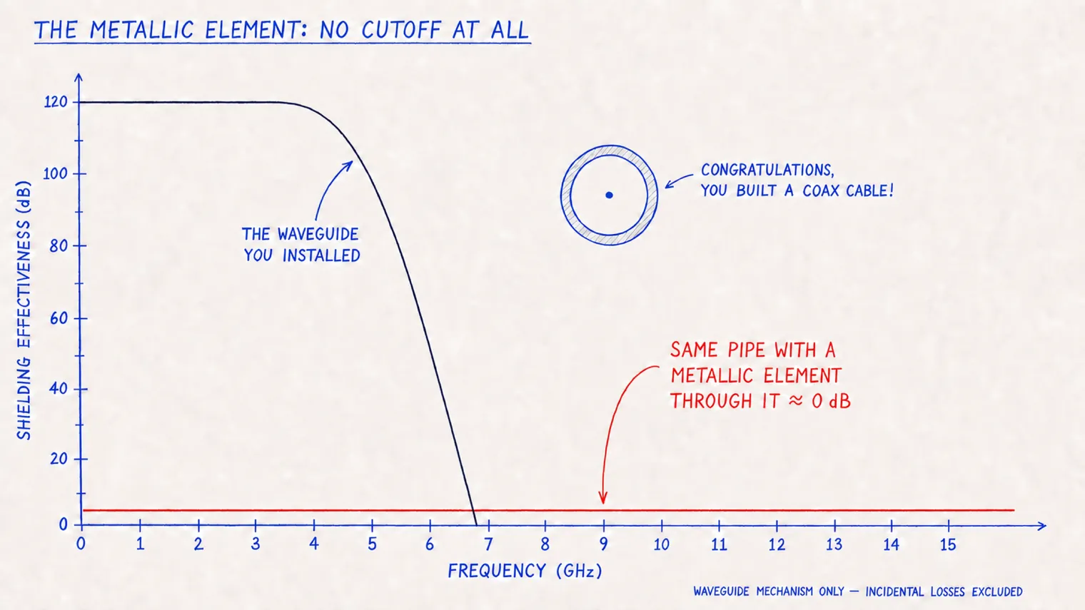
Armor. Steel strength members. Ripcords. Metallic moisture barriers. Ordinary, sensible protections for a delicate strand of glass, all hidden under the jacket where a visual inspection will never find them. It is not unusual to mistake traditional fiber cables with metallic strength or armor elements for special All Dielectric Self-Supporting (ADSS) fiber cables.
Now step back and admire what you've built. A waveguide through your shield wall and a fiber cable with a conductive protection running down the middle. An outer conductor, a center conductor and a gap between them. Sound familiar? It is on the back of your TV (if you’re old enough to remember cable TV!). This time you did not degrade your waveguide. You did not lower the Cutoff Frequency. You destroyed it because you turned your waveguide into a coax cable. And coax is famously good at carrying every frequency from DC on up.
It gets worse. That conductor does not stop at the wall. The cable run outside the facility collects ambient RF like any long wire antenna and delivers it inside. The run inside collects your emanations and delivers them out. That is a two-way antenna system through your shield: unpowered and invisible to visual inspection.
The Media Converter Problem
The untidy truth. Unless both endpoints speak native optical Ethernet, every Fiber link needs conversion at both ends: two media converters, two power supplies, jumpers and SFP transceivers, per link. Somewhere behind that rack is a nest of wall-warts and patch cords that makes a precise cable management professional feel icky. And when the accreditor shows up to physically trace every line, good luck in there. A filter mounted on the shield wall documents itself. The nest does not.
Transmitting on all channels. A media converter contains a PHY (the chip that speaks Ethernet), an oscillator and a switching power supply. You built an RF-proof Faraday cage, then installed a broadband transmitter that radiates inside and injects noise back onto facility power. Whether that matters depends on who you are. If you run an RF test chamber, you just added a handful of new ambients to your formerly quiet RF “safe space.”
No PoE over glass. Fiber does not carry power or PoE. Cameras, wireless access points and IP phones that could have utilized a simple PoE drop now need separate power runs, which means more power, wall warts, and injectors. That is not the way to simplify an installation.
The Amazon problem. Every converter is a failure point with a wall-wart. They run hot in sealed rooms, and they do not make an announcement before they go. The original installation may have used US-made media converters. But when a converter dies on a Friday afternoon, there is always an industrious maintenance tech with a company card, and the replacement is whatever unpronounceable brand Amazon can deliver by tomorrow. Same day, if you're lucky. Now that is what is guarding the boundary. A spec is only as durable as the facility's worst day, and Section 889 of the FY2019 NDAA and Section 5949 of the FY2023 NDAA (National Defense Authorization Act) have opinions about the no-name commodity converter tier.
What’s the Alternative?
Follow the rules. The current publicly available Intelligence Community Technical Specifications for SCIF construction do not require every signal line crossing the perimeter to be fiber. The Fiber Default is a habit, not a mandate.
ACTIV Filters. For Ethernet penetrating a shield wall there is exactly one alternative to the Fiber system: an active EMI filter built specifically for Ethernet. The DJM Electronics ACTIV filters work on a different principle than a waveguide. Nothing passes through. The Ethernet signal is stopped at the boundary and completely rebuilt on the other side, delivering 100 dB of shielding effectiveness from 10 kHz to 40 GHz, straight through the frequencies where connector-sized waveguides gave up long ago. Unlike the media converters, the entire filter is designed to suppress both radiated and conducted emissions, inside and out. Rebuilding instead of passing through also has a bonus. The two sides are galvanically isolated: no ground loop, no common-mode path, no electrical connection between the inside and outside networks. RJ45 on both sides. Your existing CAT infrastructure. A PoE variant. One hole in the shield. And test data to hand your accreditor.
Pasif Filters. For more relaxed shielding environments, our Pasif 1G filters are the modest, tested upgrade for past installations where "CAT 6 through a waveguide used to pass."
Conclusion. That completes the real comparison of “Fiber vs Copper.” On one side: converters, transceivers, power supplies, patch cords and a waveguide whose actual performance depends on connector size, fill and whether anyone checked the cable for metal. On the other: the copper you already have and a characterized filter with performance specs on the datasheet. That is the whole argument.
Breaking the Fiber Default
We are not anti-Fiber. We are anti-autopilot.
Copper deserves the head-to-head comparison whenever
- the run is short
- the endpoint is natively copper
- PoE is required
- conversion would put active equipment inside the SCIF
- the signal is analog, serial, USB, audio or control, or
- a tested isolation device provides the required protection.
That covers a lot of real installations.
The Fiber Default survives because nobody runs the comparison. Run the comparison. Check the frequencies. Pick the better answer on purpose. Sometimes it will still be Fiber. Fine. At least this time it was a decision. The Fiber Default does not get broken by a memo. It gets broken one informed penetration at a time.
Where This Applies
Choosing filtered copper over a fiber run pays off most in the facilities where this comparison actually gets tested:
Running the Comparison?
Send us the endpoints, the data rate and the wall construction. We’ll tell you whether a filtered copper penetration fits — and when Fiber is still the right answer.